The Scientist and Engineer's Guide to
Digital Signal Processing
By Steven W. Smith, Ph.D.
Book Search
Table of contents
- 1: The Breadth and Depth of DSP
- 2: Statistics, Probability and Noise
- 3: ADC and DAC
- 4: DSP Software
- 5: Linear Systems
- 6: Convolution
- 7: Properties of Convolution
- 8: The Discrete Fourier Transform
- 9: Applications of the DFT
- 10: Fourier Transform Properties
- 11: Fourier Transform Pairs
- 12: The Fast Fourier Transform
- 13: Continuous Signal Processing
- 14: Introduction to Digital Filters
- 15: Moving Average Filters
- 16: Windowed-Sinc Filters
- 17: Custom Filters
- 18: FFT Convolution
- 19: Recursive Filters
- 20: Chebyshev Filters
- 21: Filter Comparison
- 22: Audio Processing
- 23: Image Formation & Display
- 24: Linear Image Processing
- 25: Special Imaging Techniques
- 26: Neural Networks (and more!)
- 27: Data Compression
- 28: Digital Signal Processors
- 29: Getting Started with DSPs
- 30: Complex Numbers
- 31: The Complex Fourier Transform
- 32: The Laplace Transform
- 33: The z-Transform
- 34: Explaining Benford's Law
How to order your own hardcover copy
Wouldn't you rather have a bound book instead of 640 loose pages?Your laser printer will thank you!
Order from Amazon.com.
Chapter 12: The Fast Fourier Transform
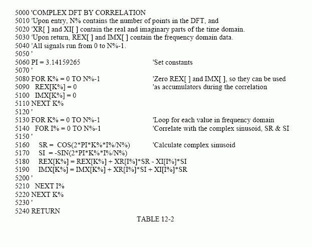
As discussed in Chapter 8, the real DFT can be calculated by correlating the time domain signal with sine and cosine waves (see Table 8-2). Table 12-2 shows a program to calculate the complex DFT by the same method. In an apples-to-apples comparison, this is the program that the FFT improves upon.
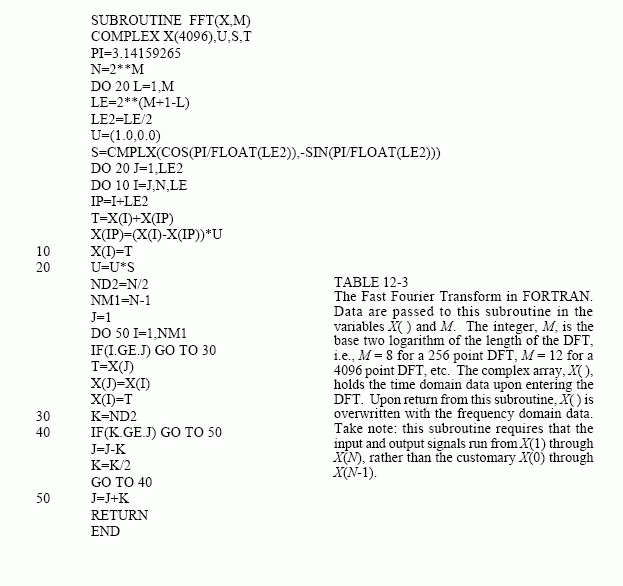
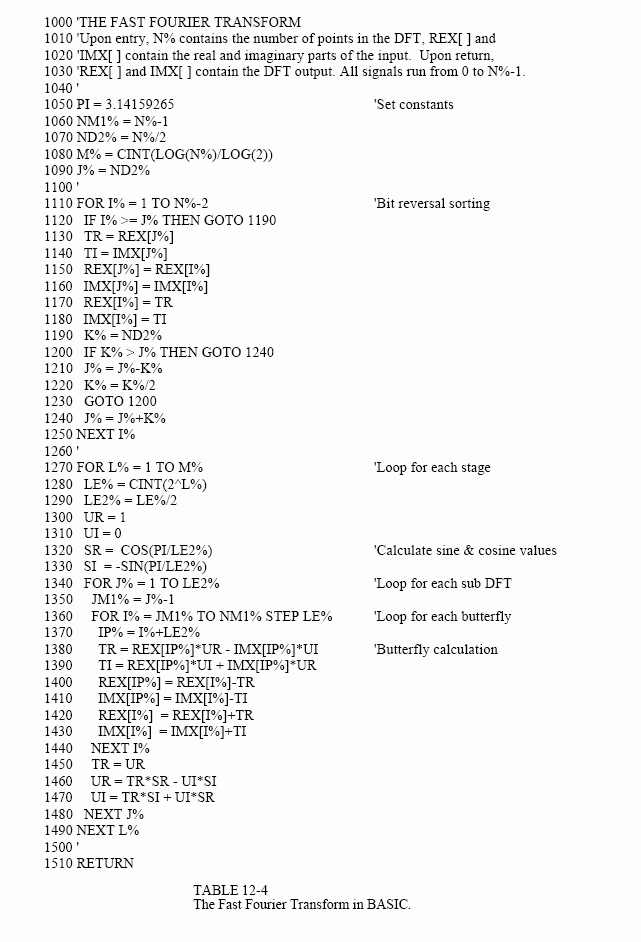
Tables 12-3 and 12-4 show two different FFT programs, one in FORTRAN and one in BASIC. First we will look at the BASIC routine in Table 12-4. This subroutine produces exactly the same output as the correlation technique in Table 12-2, except it does it much faster. The block diagram in Fig. 12-7 can be used to identify the different sections of this program. Data are passed to this FFT subroutine in the arrays: REX[ ] and IMX[ ], each running from sample 0 to N-1. Upon return from the subroutine, REX[ ] and IMX[ ] are overwritten with the frequency domain data. This is another way that the FFT is highly optimized; the same arrays are used for the input, intermediate storage, and output. This efficient use of memory is important for designing fast hardware to calculate the FFT. The term in-place computation is used to describe this memory usage.
While all FFT programs produce the same numerical result, there are subtle variations in programming that you need to look out for. Several of these

important differences are illustrated by the FORTRAN program listed in Table 12-3. This program uses an algorithm called decimation in frequency, while the previously described algorithm is called decimation in time. In a decimation in frequency algorithm, the bit reversal sorting is done after the three nested loops. There are also FFT routines that completely eliminate the bit reversal sorting. None of these variations significantly improve the performance of the FFT, and you shouldn't worry about which one you are using.
The important differences between FFT algorithms concern how data are passed to and from the subroutines. In the BASIC program, data enter and leave the subroutine in the arrays REX[ ] and IMX[ ], with the samples running from index 0 to N-1. In the FORTRAN program, data are passed in the complex array X( ), with the samples running from 1 to N. Since this is an array of complex variables, each sample in X( ) consists of two numbers, a real part and an imaginary part. The length of the DFT must also be passed to these subroutines. In the BASIC program, the variable N% is used for this purpose. In comparison, the FORTRAN program uses the variable M, which is defined to equal Log2N. For instance, M will be


8 for a 256 point DFT, 12 for a 4096 point DFT, etc. The point is, the programmer who writes an FFT subroutine has many options for interfacing with the host program. Arrays that run from 1 to N, such as in the FORTRAN program, are especially aggravating. Most of the DSP literature (including this book) explains algorithms assuming the arrays run from sample 0 to N-1. For instance, if the arrays run from 1 to N, the symmetry in the frequency domain is around points 1 and N/2 + 1, rather than points 0 and N/2.
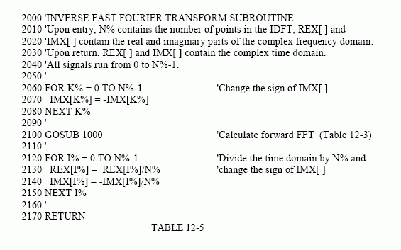
Using the complex DFT to calculate the real DFT has another interesting advantage. The complex DFT is more symmetrical between the time and frequency domains than the real DFT. That is, the duality is stronger. Among other things, this means that the Inverse DFT is nearly identical to the Forward DFT. In fact, the easiest way to calculate an Inverse FFT is to calculate a Forward FFT, and then adjust the data. Table 12-5 shows a subroutine for calculating the Inverse FFT in this manner.
Suppose you copy one of these FFT algorithms into your computer program and start it running. How do you know if it is operating properly? Two tricks are commonly used for debugging. First, start with some arbitrary time domain signal, such as from a random number generator, and run it through the FFT. Next, run the resultant frequency spectrum through the Inverse FFT and compare the result with the original signal. They should be identical, except round-off noise (a few parts-per-million for single precision).
The second test of proper operation is that the signals have the correct symmetry. When the imaginary part of the time domain signal is composed of all zeros (the normal case), the frequency domain of the complex DFT will be symmetrical around samples 0 and N/2, as previously described.

Likewise, when this correct symmetry is present in the frequency domain, the Inverse DFT will produce a time domain that has an imaginary part composes of all zeros (plus round-off noise). These debugging techniques are essential for using the FFT; become familiar with them.
