The Scientist and Engineer's Guide to
Digital Signal Processing
By Steven W. Smith, Ph.D.
Book Search
Table of contents
- 1: The Breadth and Depth of DSP
- 2: Statistics, Probability and Noise
- 3: ADC and DAC
- 4: DSP Software
- 5: Linear Systems
- 6: Convolution
- 7: Properties of Convolution
- 8: The Discrete Fourier Transform
- 9: Applications of the DFT
- 10: Fourier Transform Properties
- 11: Fourier Transform Pairs
- 12: The Fast Fourier Transform
- 13: Continuous Signal Processing
- 14: Introduction to Digital Filters
- 15: Moving Average Filters
- 16: Windowed-Sinc Filters
- 17: Custom Filters
- 18: FFT Convolution
- 19: Recursive Filters
- 20: Chebyshev Filters
- 21: Filter Comparison
- 22: Audio Processing
- 23: Image Formation & Display
- 24: Linear Image Processing
- 25: Special Imaging Techniques
- 26: Neural Networks (and more!)
- 27: Data Compression
- 28: Digital Signal Processors
- 29: Getting Started with DSPs
- 30: Complex Numbers
- 31: The Complex Fourier Transform
- 32: The Laplace Transform
- 33: The z-Transform
- 34: Explaining Benford's Law
How to order your own hardcover copy
Wouldn't you rather have a bound book instead of 640 loose pages?Your laser printer will thank you!
Order from Amazon.com.
Chapter 3: ADC and DAC
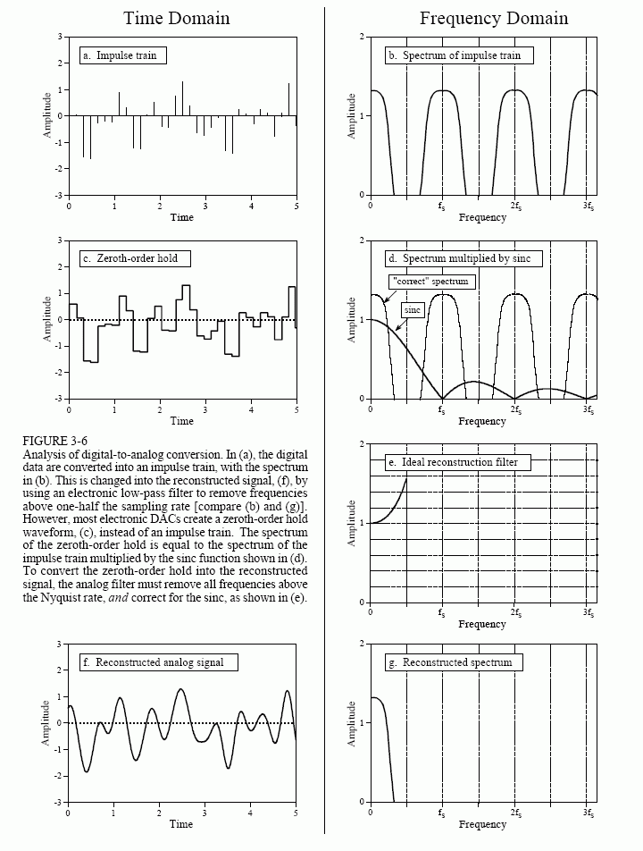
In theory, the simplest method for digital-to-analog conversion is to pull the samples from memory and convert them into an impulse train. This is

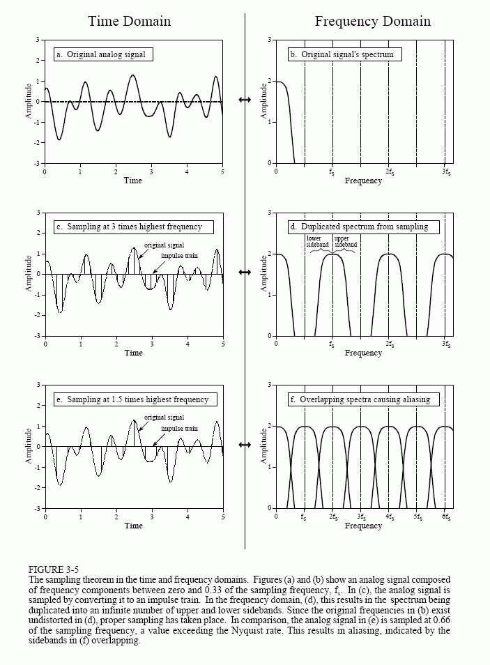
illustrated in Fig. 3-6a, with the corresponding frequency spectrum in (b). As just described, the original analog signal can be perfectly reconstructed by passing this impulse train through a low-pass filter, with the cutoff frequency equal to one-half of the sampling rate. In other words, the original signal and the impulse train have identical frequency spectra below the Nyquist frequency (one-half the sampling rate). At higher frequencies, the impulse train contains a duplication of this information, while the original analog signal contains nothing (assuming aliasing did not occur).
While this method is mathematically pure, it is difficult to generate the required narrow pulses in electronics. To get around this, nearly all DACs operate by holding the last value until another sample is received. This is called a zeroth-order hold, the DAC equivalent of the sample-and-hold used during ADC. (A first-order hold is straight lines between the points, a second-order hold uses parabolas, etc.). The zeroth-order hold produces the staircase appearance shown in (c).
In the frequency domain, the zeroth-order hold results in the spectrum of the impulse train being multiplied by the dark curve shown in (d), given by the equation:

This is of the general form: sin(πx)/(πx), called the sinc function or sinc(x). The sinc function is very common in DSP, and will be discussed in more detail in later chapters. If you already have a background in this material, the zeroth-order hold can be understood as the convolution of the impulse train with a rectangular pulse, having a width equal to the sampling period. This results in the frequency domain being multiplied by the Fourier transform of the rectangular pulse, i.e., the sinc function. In Fig. (d), the light line shows the frequency spectrum of the impulse train (the "correct" spectrum), while the dark line shown the sinc. The frequency spectrum of the zeroth order hold signal is equal to the product of these two curves.
The analog filter used to convert the zeroth-order hold signal, (c), into the reconstructed signal, (f), needs to do two things: (1) remove all frequencies above one-half of the sampling rate, and (2) boost the frequencies by the reciprocal of the zeroth-order hold's effect, i.e., 1/sinc(x). This amounts to an amplification of about 36% at one-half of the sampling frequency. Figure (e) shows the ideal frequency response of this analog filter.
This 1/sinc(x) frequency boost can be handled in four ways: (1) ignore it and accept the consequences, (2) design an analog filter to include the 1/sinc(x)

response, (3) use a fancy multirate technique described later in this chapter, or (4) make the correction in software before the DAC (see Chapter 24).
Before leaving this section on sampling, we need to dispel a common myth about analog versus digital signals. As this chapter has shown, the amount of information carried in a digital signal is limited in two ways: First, the number of bits per sample limits the resolution of the dependent variable. That is, small changes in the signal's amplitude may be lost in the quantization noise. Second, the sampling rate limits the resolution of the independent variable, i.e., closely spaced events in the analog signal may be lost between the samples. This is another way of saying that frequencies above one-half the sampling rate are lost.
Here is the myth: "Since analog signals use continuous parameters, they have infinitely good resolution in both the independent and the dependent variables." Not true! Analog signals are limited by the same two problems as digital signals: noise and bandwidth (the highest frequency allowed in the signal). The noise in an analog signal limits the measurement of the waveform's amplitude, just as quantization noise does in a digital signal. Likewise, the ability to separate closely spaced events in an analog signal depends on the highest frequency allowed in the waveform. To understand this, imagine an analog signal containing two closely spaced pulses. If we place the signal through a low-pass filter (removing the high frequencies), the pulses will blur into a single blob. For instance, an analog signal formed from frequencies between DC and 10 kHz will have exactly the same resolution as a digital signal sampled at 20 kHz. It must, since the sampling theorem guarantees that the two contain the same information.
