The Scientist and Engineer's Guide to
Digital Signal Processing
By Steven W. Smith, Ph.D.
Book Search
Table of contents
- 1: The Breadth and Depth of DSP
- 2: Statistics, Probability and Noise
- 3: ADC and DAC
- 4: DSP Software
- 5: Linear Systems
- 6: Convolution
- 7: Properties of Convolution
- 8: The Discrete Fourier Transform
- 9: Applications of the DFT
- 10: Fourier Transform Properties
- 11: Fourier Transform Pairs
- 12: The Fast Fourier Transform
- 13: Continuous Signal Processing
- 14: Introduction to Digital Filters
- 15: Moving Average Filters
- 16: Windowed-Sinc Filters
- 17: Custom Filters
- 18: FFT Convolution
- 19: Recursive Filters
- 20: Chebyshev Filters
- 21: Filter Comparison
- 22: Audio Processing
- 23: Image Formation & Display
- 24: Linear Image Processing
- 25: Special Imaging Techniques
- 26: Neural Networks (and more!)
- 27: Data Compression
- 28: Digital Signal Processors
- 29: Getting Started with DSPs
- 30: Complex Numbers
- 31: The Complex Fourier Transform
- 32: The Laplace Transform
- 33: The z-Transform
- 34: Explaining Benford's Law
How to order your own hardcover copy
Wouldn't you rather have a bound book instead of 640 loose pages?Your laser printer will thank you!
Order from Amazon.com.
Chapter 3: ADC and DAC
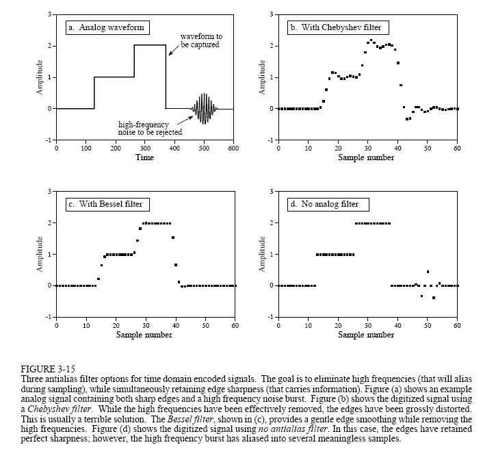
There is a strong trend in electronics to replace analog circuitry with digital algorithms. Data conversion is an excellent example of this. Consider the design of a digital voice recorder, a system that will digitize a voice signal, store the data in digital form, and later reconstruct the signal for playback. To recreate intelligible speech, the system must capture the frequencies between about 100 and 3000 hertz. However, the analog signal produced by the microphone also contains much higher frequencies, say to 40 kHz. The brute force approach is to pass the analog signal through an eight pole low-pass Chebyshev filter at 3 kHz, and then sample at 8 kHz. On the other end, the DAC reconstructs the analog signal at 8 kHz with a zeroth order hold. Another Chebyshev filter at 3 kHz is used to produce the final voice signal.

There are many useful benefits in sampling faster than this direct analysis. For example, imagine redesigning the digital voice recorder using a 64 kHz sampling rate. The antialias filter now has an easier task: pass all freq-uencies below 3 kHz, while rejecting all frequencies above 32 kHz. A similar simplification occurs for the reconstruction filter. In short, the higher sampling rate allows the eight pole filters to be replaced with simple RC networks. The problem is, the digital system is now swamped with data from the higher sampling rate.
The next level of sophistication involves multirate techniques, using more than one sampling rate in the same system. It works like this for the digital voice recorder example. First, pass the voice signal through a simple RC low-pass filter and sample the data at 64 kHz. The resulting digital data contains the desired voice band between 100 and 3000 hertz, but also has an unusable band between 3 kHz and 32 kHz. Second, remove these unusable frequencies in software, by using a digital low-pass filter at 3 kHz. Third, resample the digital signal from 64 kHz to 8 kHz by simply discarding every seven out of eight samples, a procedure called decimation. The resulting digital data is equivalent to that produced by aggressive analog filtering and direct 8 kHz sampling.
Multirate techniques can also be used in the output portion of our example system. The 8 kHz data is pulled from memory and converted to a 64 kHz sampling rate, a procedure called interpolation. This involves placing seven samples, with a value of zero, between each of the samples obtained from memory. The resulting signal is a digital impulse train, containing the desired voice band between 100 and 3000 hertz, plus spectral duplications between 3 kHz and 32 kHz. Refer back to Figs. 3-6 a&b to understand why this it true. Everything above 3 kHz is then removed with a digital low-pass filter. After conversion to an analog signal through a DAC, a simple RC network is all that is required to produce the final voice signal.
Multirate data conversion is valuable for two reasons: (1) it replaces analog components with software, a clear economic advantage in mass-produced products, and (2) it can achieve higher levels of performance in critical applications. For example, compact disc audio systems use techniques of this type to achieve the best possible sound quality. This increased performance is a result of replacing analog components (1% precision), with digital algorithms (0.0001% precision from round-off error). As discussed in upcoming chapters, digital filters outperform analog filters by hundreds of times in key areas.
