The Scientist and Engineer's Guide to
Digital Signal Processing
By Steven W. Smith, Ph.D.
Book Search
Table of contents
- 1: The Breadth and Depth of DSP
- 2: Statistics, Probability and Noise
- 3: ADC and DAC
- 4: DSP Software
- 5: Linear Systems
- 6: Convolution
- 7: Properties of Convolution
- 8: The Discrete Fourier Transform
- 9: Applications of the DFT
- 10: Fourier Transform Properties
- 11: Fourier Transform Pairs
- 12: The Fast Fourier Transform
- 13: Continuous Signal Processing
- 14: Introduction to Digital Filters
- 15: Moving Average Filters
- 16: Windowed-Sinc Filters
- 17: Custom Filters
- 18: FFT Convolution
- 19: Recursive Filters
- 20: Chebyshev Filters
- 21: Filter Comparison
- 22: Audio Processing
- 23: Image Formation & Display
- 24: Linear Image Processing
- 25: Special Imaging Techniques
- 26: Neural Networks (and more!)
- 27: Data Compression
- 28: Digital Signal Processors
- 29: Getting Started with DSPs
- 30: Complex Numbers
- 31: The Complex Fourier Transform
- 32: The Laplace Transform
- 33: The z-Transform
- 34: Explaining Benford's Law
How to order your own hardcover copy
Wouldn't you rather have a bound book instead of 640 loose pages?Your laser printer will thank you!
Order from Amazon.com.
Chapter 4: DSP Software
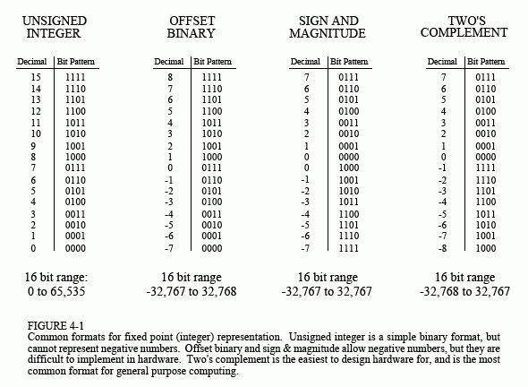
Fixed point representation is used to store integers, the positive and negative whole numbers: … -3, -2, -1, 0, 1, 2, 3, …. High level programs, such as C and BASIC, usually allocate 16 bits to store each integer. In the simplest case, the 216 = 65,536 possible bit patterns are assigned to the numbers 0 through 65,535. This is called unsigned integer format, and a simplified example is shown in Fig. 4-1 (using only 4 bits per number). Conversion between the bit pattern and the number being represented is nothing more than changing between base 2 (binary) and base 10 (decimal). The disadvantage of unsigned integer is that negative numbers cannot be represented.
Offset binary is similar to unsigned integer, except the decimal values are shifted to allow for negative numbers. In the 4 bit example of Fig. 4-1, the decimal numbers are offset by seven, resulting in the 16 bit patterns corresponding to the integer numbers -7 through 8. In this same manner, a 16 bit representation would use 32,767 as an offset, resulting in a range between -32,767 and 32,768. Offset binary is not a standardized format, and you will find other offsets used, such 32,768. The most important use of offset binary is in ADC and DAC. For example, the input voltage range of -5v to 5v might be mapped to the digital numbers 0 to 4095, for a 12 bit conversion.
Sign and magnitude is another simple way of representing negative integers. The far left bit is called the sign bit, and is made a zero for positive numbers, and a one for negative numbers. The other bits are a standard binary representation of the absolute value of the number. This results in one wasted bit pattern, since there are two representations for zero, 0000 (positive zero) and 1000 (negative zero). This encoding scheme results in 16 bit numbers having a range of -32,767 to 32,767.

These first three representations are conceptually simple, but difficult to implement in hardware. Remember, when A=B+C is entered into a computer program, some hardware engineer had to figure out how to make the bit pattern representing B, combine with the bit pattern representing C, to form the bit pattern representing A.
Two's complement is the format loved by hardware engineers, and is how integers are usually represented in computers. To understand the encoding pattern, look first at decimal number zero in Fig. 4-1, which corresponds to a binary zero, 0000. As we count upward, the decimal number is simply the binary equivalent (0 = 0000, 1 = 0001, 2 = 0010, 3 = 0011, etc.). Now, remember that these four bits are stored in a register consisting of 4 flip-flops. If we again start at 0000 and begin subtracting, the digital hardware automatically counts in two's complement: 0 = 0000, -1 = 1111, -2 = 1110, -3 = 1101, etc. This is analogous to the odometer in a new automobile. If driven forward, it changes: 00000, 00001, 00002, 00003, and so on. When driven backwards, the odometer changes: 00000, 99999, 99998, 99997, etc.
Using 16 bits, two's complement can represent numbers from -32,768 to 32,767. The left most bit is a 0 if the number is positive or zero, and a 1 if the number is negative. Consequently, the left most bit is called the sign bit, just as in sign & magnitude representation. Converting between decimal and two's complement is straightforward for positive numbers, a simple decimal to binary conversion. For negative numbers, the following algorithm is often used: (1) take the absolute value of the decimal number, (2) convert it to binary, (3) complement all of the bits (ones become zeros and zeros become ones), (4) add 1 to the binary number. For example: -5 → 5 → 0101 → 1010 → 1011. Two's complement is hard for humans, but easy for digital electronics.
