The Scientist and Engineer's Guide to
Digital Signal Processing
By Steven W. Smith, Ph.D.
Book Search
Table of contents
- 1: The Breadth and Depth of DSP
- 2: Statistics, Probability and Noise
- 3: ADC and DAC
- 4: DSP Software
- 5: Linear Systems
- 6: Convolution
- 7: Properties of Convolution
- 8: The Discrete Fourier Transform
- 9: Applications of the DFT
- 10: Fourier Transform Properties
- 11: Fourier Transform Pairs
- 12: The Fast Fourier Transform
- 13: Continuous Signal Processing
- 14: Introduction to Digital Filters
- 15: Moving Average Filters
- 16: Windowed-Sinc Filters
- 17: Custom Filters
- 18: FFT Convolution
- 19: Recursive Filters
- 20: Chebyshev Filters
- 21: Filter Comparison
- 22: Audio Processing
- 23: Image Formation & Display
- 24: Linear Image Processing
- 25: Special Imaging Techniques
- 26: Neural Networks (and more!)
- 27: Data Compression
- 28: Digital Signal Processors
- 29: Getting Started with DSPs
- 30: Complex Numbers
- 31: The Complex Fourier Transform
- 32: The Laplace Transform
- 33: The z-Transform
- 34: Explaining Benford's Law
How to order your own hardcover copy
Wouldn't you rather have a bound book instead of 640 loose pages?Your laser printer will thank you!
Order from Amazon.com.
Chapter 5: Linear Systems
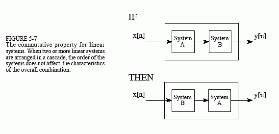
Linearity is commutative, a property involving the combination of two or more systems. Figure 5-10 shows the general idea. Imagine two systems combined in a cascade, that is, the output of one system is the input to the next. If each system is linear, then the overall combination will also be linear. The commutative property states that the order of the systems in the cascade can be rearranged without affecting the characteristics of the overall combination. You probably have used this principle in electronic circuits. For example, imagine a circuit composed of two stages, one for amplification, and one for filtering. Which is best, amplify and then filter, or filter and then amplify? If both stages are linear, the order doesn't make any difference and the overall result is the same. Keep in mind that actual electronics has nonlinear effects that may make the order important, for instance: interference, DC offsets, internal noise, slew rate distortion, etc.

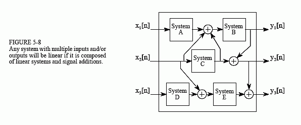
Figure 5-8 shows the next step in linear system theory: multiple inputs and outputs. A system with multiple inputs and/or outputs will be linear if it is composed of linear subsystems and additions of signals. The complexity does not matter, only that nothing nonlinear is allowed inside of the system.
To understand what linearity means for systems with multiple inputs and/or outputs, consider the following thought experiment. Start by placing a signal on one input while the other inputs are held at zero. This will cause the multiple outputs to respond with some pattern of signals. Next, repeat the procedure by placing another signal on a different input. Just as before, keep all of the other inputs at zero. This second input signal will result in another pattern of signals appearing on the multiple outputs. To finish the experiment, place both signals on their respective inputs simultaneously. The signals appearing on the outputs will simply be the superposition (sum) of the output signals produced when the input signals were applied separately.

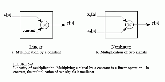
The use of multiplication in linear systems is frequently misunderstood. This is because multiplication can be either linear or nonlinear, depending on what the signal is multiplied by. Figure 5-9 illustrates the two cases. A system that multiplies the input signal by a constant, is linear. This system is an amplifier or an attenuator, depending if the constant is greater or less than one, respectively. In contrast, multiplying a signal by another signal is nonlinear. Imagine a sinusoid multiplied by another sinusoid; the resulting waveform is clearly not sinusoidal.
Another commonly misunderstood situation relates to parasitic signals added in electronics, such as DC offsets and thermal noise. Is the addition of these extraneous signals linear or nonlinear? The answer depends on where the contaminating signals are viewed as originating. If they are viewed as coming from within the system, the process is nonlinear. This is because a sinusoidal input does not produce a pure sinusoidal output. Conversely, the extraneous signal can be viewed as externally entering the system on a separate input of a multiple input system. This makes the process linear, since only a signal addition is required within the system.

