The Scientist and Engineer's Guide to
Digital Signal Processing
By Steven W. Smith, Ph.D.
Book Search
Table of contents
- 1: The Breadth and Depth of DSP
- 2: Statistics, Probability and Noise
- 3: ADC and DAC
- 4: DSP Software
- 5: Linear Systems
- 6: Convolution
- 7: Properties of Convolution
- 8: The Discrete Fourier Transform
- 9: Applications of the DFT
- 10: Fourier Transform Properties
- 11: Fourier Transform Pairs
- 12: The Fast Fourier Transform
- 13: Continuous Signal Processing
- 14: Introduction to Digital Filters
- 15: Moving Average Filters
- 16: Windowed-Sinc Filters
- 17: Custom Filters
- 18: FFT Convolution
- 19: Recursive Filters
- 20: Chebyshev Filters
- 21: Filter Comparison
- 22: Audio Processing
- 23: Image Formation & Display
- 24: Linear Image Processing
- 25: Special Imaging Techniques
- 26: Neural Networks (and more!)
- 27: Data Compression
- 28: Digital Signal Processors
- 29: Getting Started with DSPs
- 30: Complex Numbers
- 31: The Complex Fourier Transform
- 32: The Laplace Transform
- 33: The z-Transform
- 34: Explaining Benford's Law
How to order your own hardcover copy
Wouldn't you rather have a bound book instead of 640 loose pages?Your laser printer will thank you!
Order from Amazon.com.
Chapter 8: The Discrete Fourier Transform
As it has been described so far, the frequency domain is a group of amplitudes of cosine and sine waves (with slight scaling modifications). This is called rectangular notation. Alternatively, the frequency domain can be expressed in polar form. In this notation, ReX[ ] & ImX[ ] are replaced with two other arrays, called the Magnitude of X[ ] , written in equations as: Mag X[ ], and the Phase of X[ ], written as: Phase X[ ]. The magnitude and phase are a pair-for-pair replacement for the real and imaginary parts. For example, Mag X[0] and Phase X[0] are calculated using only ReX[0] and ImX[0]. Likewise, Mag X[14] and Phase X[14] are calculated using only ReX[14] and ImX[14], and so forth. To understand the conversion, consider what happens when you add a cosine wave and a sine wave of the same frequency. The result is a cosine wave of the same frequency, but with a new amplitude and a phase shift. In equation form, the two representations are related:

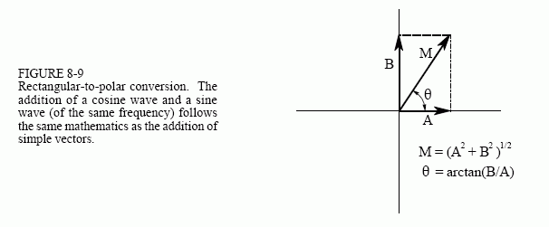
The important point is that no information is lost in this process; given one representation you can calculate the other. In other words, the information contained in the amplitudes A and B, is also contained in the variables M and θ. Although this equation involves sine and cosine waves, it follows the same conversion equations as do simple vectors. Figure 8-9 shows the analogous vector representation of how the two variables, A and B, can be viewed in a rectangular coordinate system, while M and θ are parameters in polar coordinates.

In polar notation, Mag X[ ] holds the amplitude of the cosine wave (M in Eq. 8-4 and Fig. 8-9), while Phase X[ ] holds the phase angle of the cosine wave (θ in Eq. 8-4 and Fig. 8-9). The following equations convert the frequency domain from rectangular to polar notation, and vice versa:


Rectangular and polar notation allow you to think of the DFT in two different ways. With rectangular notation, the DFT decomposes an N point signal into N/2 + 1 cosine waves and N/2 + 1 sine waves, each with a specified amplitude. In polar notation, the DFT decomposes an N point signal into N/2 + 1 cosine waves, each with a specified amplitude (called the magnitude) and phase shift. Why does polar notation use cosine waves instead of sine waves? Sine waves cannot represent the DC component of a signal, since a sine wave of zero frequency is composed of all zeros (see Figs. 8-5 a&b).
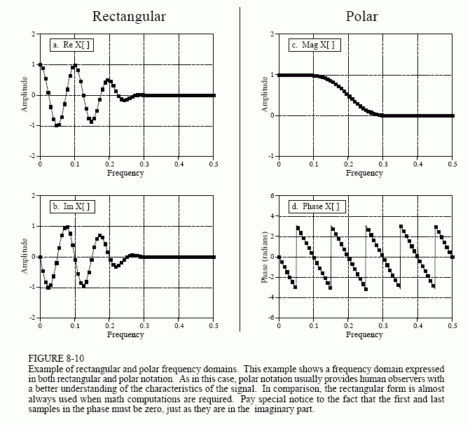
Even though the polar and rectangular representations contain exactly the same information, there are many instances where one is easier to use that the other. For example, Fig. 8-10 shows a frequency domain signal in both rectangular and polar form. Warning: Don't try to understand the shape of the real and imaginary parts; your head will explode! In comparison, the polar curves are straightforward: only frequencies below about 0.25 are present, and the phase shift is approximately proportional to the frequency. This is the frequency response of a low-pass filter.

When should you use rectangular notation and when should you use polar? Rectangular notation is usually the best choice for calculations, such as in equations and computer programs. In comparison, graphs are almost always in polar form. As shown by the previous example, it is nearly impossible for humans to understand the characteristics of a frequency domain signal by looking at the real and imaginary parts. In a typical program, the frequency domain signals are kept in rectangular notation until an observer needs to look at them, at which time a rectangular-to-polar conversion is done.
Why is it easier to understand the frequency domain in polar notation? This question goes to the heart of why decomposing a signal into sinusoids is useful. Recall the property of sinusoidal fidelity from Chapter 5: if a sinusoid enters a linear system, the output will also be a sinusoid, and at exactly the same frequency as the input. Only the amplitude and phase can change. Polar notation directly represents signals in terms of the amplitude and phase of the component cosine waves. In turn, systems can be represented by how they modify the amplitude and phase of each of these cosine waves.
Now consider what happens if rectangular notation is used with this scenario. A mixture of cosine and sine waves enter the linear system, resulting in a mixture of cosine and sine waves leaving the system. The problem is, a cosine wave on the input may result in both cosine and sine waves on the output. Likewise, a sine wave on the input can result in both cosine and sine waves on the output. While these cross-terms can be straightened out, the overall method doesn't match with why we wanted to use sinusoids in the first place.
