The Scientist and Engineer's Guide to
Digital Signal Processing
By Steven W. Smith, Ph.D.
Book Search
Table of contents
- 1: The Breadth and Depth of DSP
- 2: Statistics, Probability and Noise
- 3: ADC and DAC
- 4: DSP Software
- 5: Linear Systems
- 6: Convolution
- 7: Properties of Convolution
- 8: The Discrete Fourier Transform
- 9: Applications of the DFT
- 10: Fourier Transform Properties
- 11: Fourier Transform Pairs
- 12: The Fast Fourier Transform
- 13: Continuous Signal Processing
- 14: Introduction to Digital Filters
- 15: Moving Average Filters
- 16: Windowed-Sinc Filters
- 17: Custom Filters
- 18: FFT Convolution
- 19: Recursive Filters
- 20: Chebyshev Filters
- 21: Filter Comparison
- 22: Audio Processing
- 23: Image Formation & Display
- 24: Linear Image Processing
- 25: Special Imaging Techniques
- 26: Neural Networks (and more!)
- 27: Data Compression
- 28: Digital Signal Processors
- 29: Getting Started with DSPs
- 30: Complex Numbers
- 31: The Complex Fourier Transform
- 32: The Laplace Transform
- 33: The z-Transform
- 34: Explaining Benford's Law
How to order your own hardcover copy
Wouldn't you rather have a bound book instead of 640 loose pages?Your laser printer will thank you!
Order from Amazon.com.
Chapter 9: Applications of the DFT
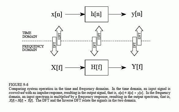
Systems are analyzed in the time domain by using convolution. A similar analysis can be done in the frequency domain. Using the Fourier transform, every input signal can be represented as a group of cosine waves, each with a specified amplitude and phase shift. Likewise, the DFT can be used to represent every output signal in a similar form. This means that any linear system can be completely described by how it changes the amplitude and phase of cosine waves passing through it. This information is called the system's frequency response. Since both the impulse response and the frequency response contain complete information about the system, there must be a one-to-one correspondence between the two. Given one, you can calculate the other. The relationship between the impulse response and the frequency response is one of the foundations of signal processing: A system's frequency response is the Fourier Transform of its impulse response. Figure 9-6 illustrates these relationships.
Keeping with standard DSP notation, impulse responses use lower case variables, while the corresponding frequency responses are upper case. Since h[ ] is the common symbol for the impulse response, H[ ] is used for the frequency response. Systems are described in the time domain by convolution, that is: x[n] ∗ h[n] = y[n]. In the frequency domain, the input spectrum is multiplied by the frequency response, resulting in the output spectrum. As an equation: X[f] × H[f] = Y[f]. In other words, convolution in the time domain corresponds to multiplication in the frequency domain.
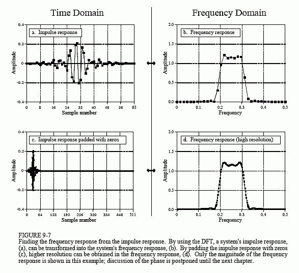
Figure 9-7 shows an example of using the DFT to convert a system's impulse response into its frequency response. Figure (a) is the impulse response of the system. Looking at this curve isn't going to give you the slightest idea what the system does. Taking a 64 point DFT of this impulse response produces the frequency response of the system, shown in (b). Now the function of this system becomes obvious, it passes frequencies between 0.2 and 0.3, and rejects all others. It is a band-pass filter. The phase of the frequency response could also be examined; however, it is more difficult to interpret and less interesting. It will be discussed in upcoming chapters.
Figure (b) is very jagged due to the low number of samples defining the curve. This situation can be improved by padding the impulse response with zeros before taking the DFT. For example, adding zeros to make the impulse response 512 samples long, as shown in (c), results in the higher resolution frequency response shown in (d).
How much resolution can you obtain in the frequency response? The answer is: infinitely high, if you are willing to pad the impulse response with an infinite number of zeros. In other words, there is nothing limiting the frequency resolution except the length of the DFT. This leads to a very important concept. Even though the impulse response is a discrete signal, the corresponding frequency response is continuous. An N point DFT of the impulse response provides N/2 + 1 samples of this continuous curve. If you make the DFT longer, the resolution improves, and you obtain a better idea of what the continuous curve looks like. Remember what the frequency response represents: amplitude and phase changes experienced by cosine waves as they pass through the system. Since the input signal can contain any frequency between 0 and 0.5, the system's frequency response must be a continuous curve over this range.


This can be better understood by bringing in another member of the Fourier transform family, the Discrete Time Fourier Transform (DTFT). Consider an N sample signal being run through an N point DFT, producing an N/2 + 1 sample frequency domain. Remember from the last chapter that the DFT considers the time domain signal to be infinitely long and periodic. That is, the N points are repeated over and over from negative to positive infinity. Now consider what happens when we start to pad the time domain signal with an ever increasing number of zeros, to obtain a finer and finer sampling in the frequency domain. Adding zeros makes the period of the time domain longer, while simultaneously making the frequency domain samples closer together.
Now we will take this to the extreme, by adding an infinite number of zeros to the time domain signal. This produces a different situation in two respects. First, the time domain signal now has an infinitely long period. In other words, it has turned into an aperiodic signal. Second, the frequency domain has achieved an infinitesimally small spacing between samples. That is, it has become a continuous signal. This is the DTFT, the procedure that changes a discrete aperiodic signal into a frequency domain that is a continuous curve. In mathematical terms, a system's frequency response is found by taking the DTFT of its impulse response. Since this cannot be done in a computer, the DFT is used to calculate a sampling of the true frequency response. This is the difference between what you do in a computer (the DFT) and what you do with mathematical equations (the DTFT).
